Software Overview

All code can be found on our GitHub:

The flight software's most important responsibility was to stabilize the aircraft. Due to the aircraft being a bi-copter, it is inherently an incredibly unstable system, being impossible to fly manually by hand. This means that the pilot needs some assistance regarding stabilization for it to be feasible to fly. There are 3 important sections to the software's architecture:

  1. Orientation Estimation
  2. Transmission and Reception of PPM signal
  3. PID logic and control mixing
Orientation Estimation

Image source: https://x-io.co.uk/downloads/madgwick_internal_report.pdf

In order for our bi-copter to be stabilized in the first place, it needs to know its orientation. This is the purpose of our 9-axis inertial measurement unit (IMU), which consists of an accelerometer, gyroscope, and magnetometer. In the real world, unprocessed IMU data is unreliable, with issues such as noise and drift, making it unpractical to work with. A solution to this is sensor fusion by algorithm, such as using a complimentary filter. A complimentary filter is a simple method that combines accelerometer and gyroscope data to estimate orientation. It does this by blending high-pass filtered gyroscope data with low-pass filtered accelerometer data using a single weight coefficient, providing a more accurate and reliable result than either sensor would individually. However, with its simplicity comes with some problems, a major one being gyroscope drift, which makes it less than ideal for our application. Another algorithm would be the Kalman filter, which estimates the state of a dynamic system by combining predictions from a mathematical model with noisy measurements, using probabilities to minimize uncertainty and optimally update the state with each new observation. However, it is difficult to implement, requiring a sophisticated model of the system, as well as being computationally expensive, which our microcontroller would not be able to run at a practical speed.

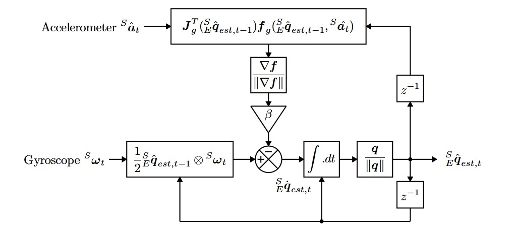
We ultimately chose to implement the Madgwick filter for orientation estimation. This algorithm employs a quaternion to describe the coupled nature of orientations in three-dimensions and is not subject to the problematic singularities associated with an Euler angle representation. The use of quaternions allows accelerometer and magnetometer data to be used in an analytically derived and optimized gradient-descent algorithm to compute the direction of the gyroscope measurement error as a quaternion derivative, allowing for the estimated angular rate of change to be more accurate, leading to more accurate orientation estimations once integrated. Its main advantages over previously mentioned filtering algorithms is that it is easy to implement, only requiring a single tunable parameter for optimal performance, produces reliable orientation estimations, has inherent gyroscopic drift compensation due to constant corrections, and is computationally cheap. With this reliable orientation data, our control loop is now able to generate proper motor and servo responses to achiever stabilization.

Decoding PPM SIgnals

Image source: https://www.researchgate.net/figure/PPM-signal-outputted-by-an-RC-receiver_fig11_327417180

The Mictrocontroller Recieves signals from the radio as PPM(Pulse Position Modulation) signals. These signals encode information by modulating the timing between signal pulses. Our reciever would encode 8 channels of data, with each channel corresponding to a button or stick on the controller. Our firmware used interrupts to capture and decode the data in the PPM signal. The intterupt triggered a flag for the microcontroller to convert the recieved channel information into updated control inputs.

PID Logic and Control Mixing

Image source: https://www.mdpi.com/2075-1702/12/5/296

We can control our orientation (pitch, yaw, roll) by altering motor speeds and servo angle. Roll is controlled by increasing one motor speed, while decreasing the other by an equivalent amount, pitch is controlled by adjusting both servo angles forward or backwards, and yaw is controlled by adjusting both servo angles in opposite directions. In our control algorithm, we focused on stabilizing pitch and roll, as these axis were deemed the most unstable. This is in contrast to yaw, which can easily be controlled by a human pilot once the aircraft is stabilized in other axes.

Our controller uses PID logic for both axes, where our desired state is the angle that is translated from PPM to degrees (taken from the transmitter). For example, if the pilot wanted to hover, the desired angle would be 0 degrees in both pitch and roll. If there is error in an axes, it gets fed into the PID loop where an output signal is produced to determine motor speed or servo angle necessary to drive the aircraft to the set point orientation. For control mixing, even though the system is very non-linear, we assumed that for small corrections during a hover, that linearly combining pitch and roll corrections together would have desirable results. Modeling and simulation in Simulink was able to prove that this would work well enough for our case. In order to test this logic we put our Iron Bird prototype into a testing gimble. While this does not perfectly simulate the dynamics of our system it provided a proof of concept that we could control our system in this way.