Design Priorities

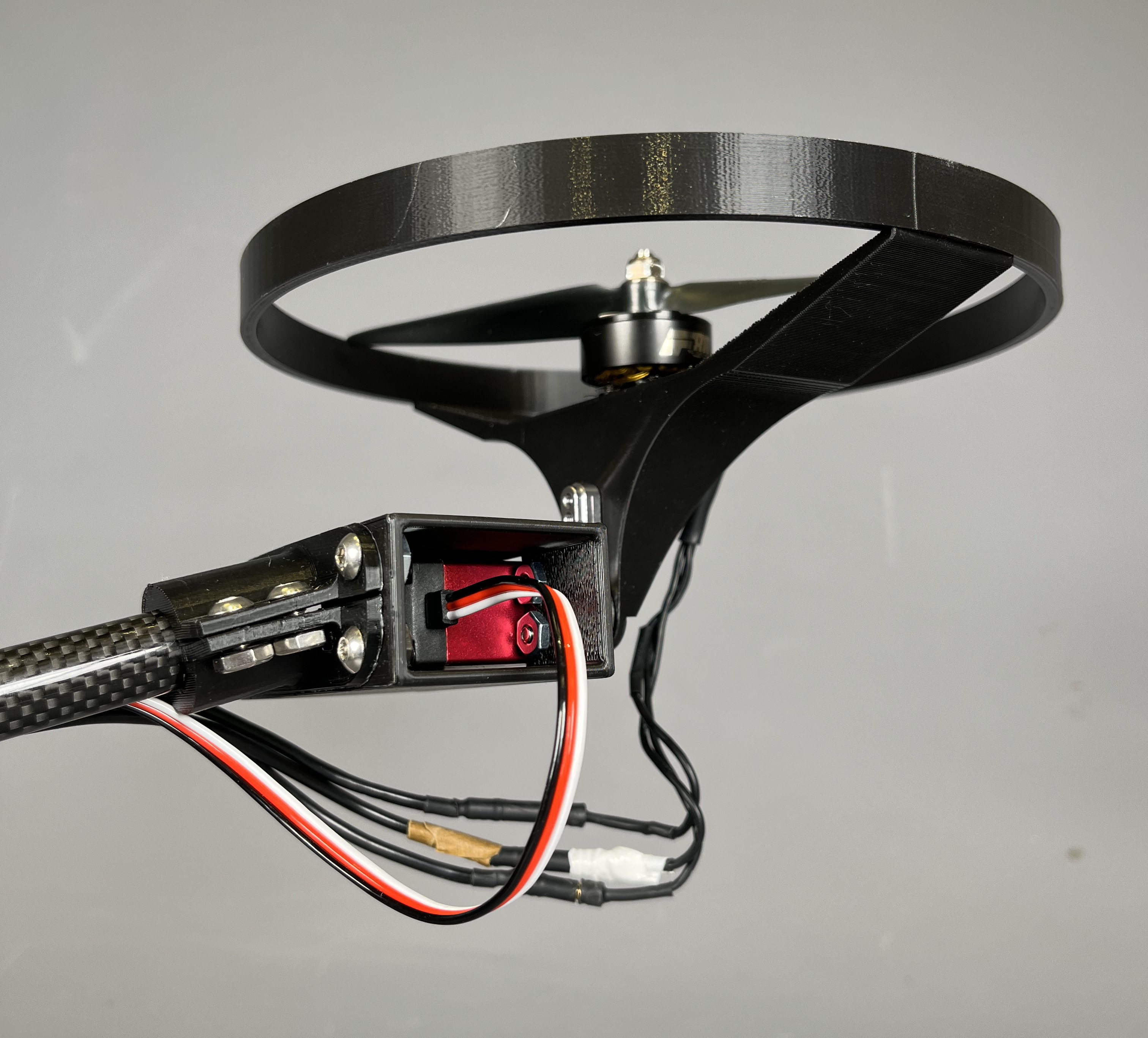
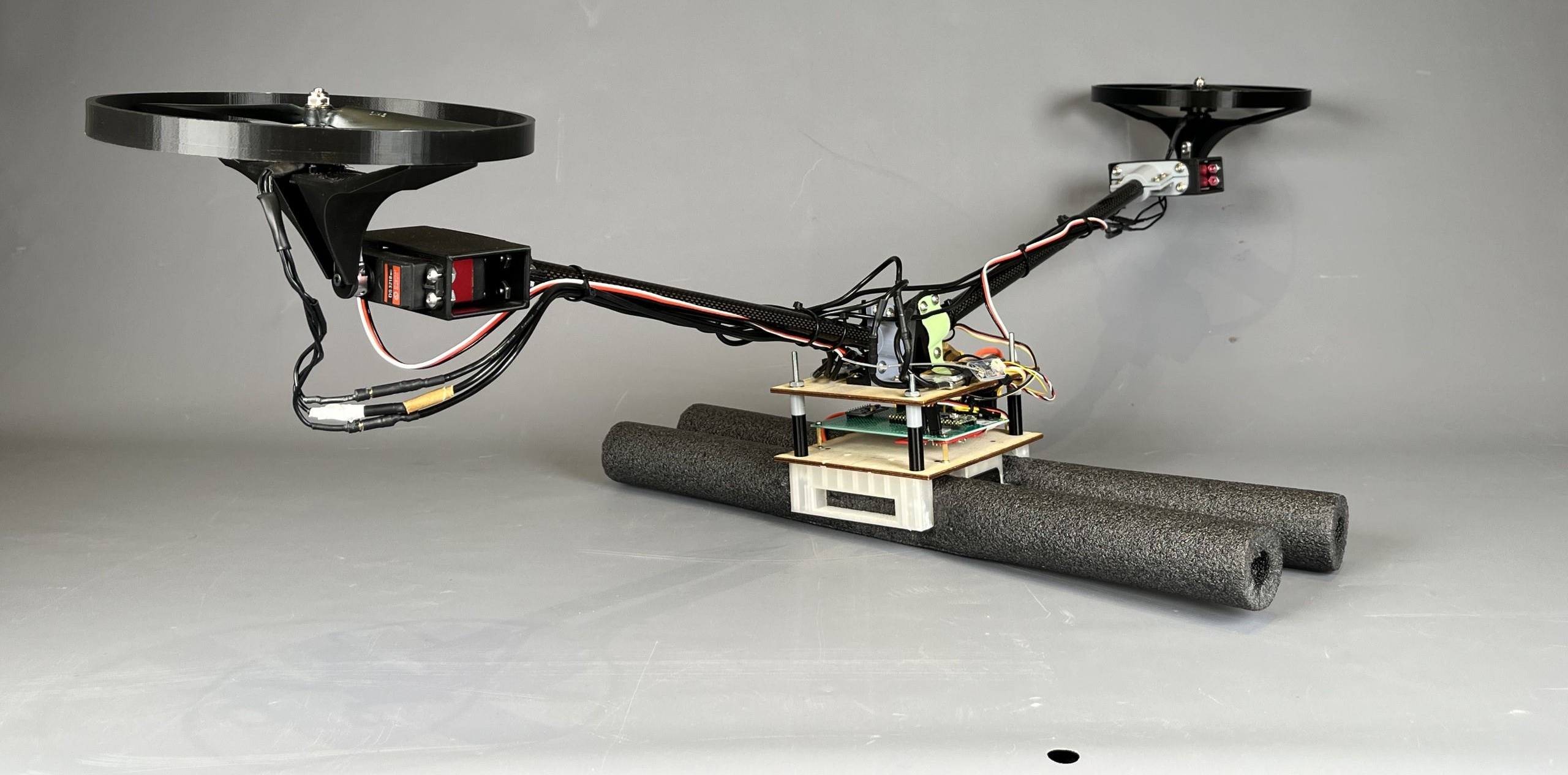
The priorities for this mechanical design were light weight, stiffness, and resilience. As a bicopter, the vehicle mounts a pair of drone motors to servos on PLA printed motor mounts, which connect the servo horn and the motors, with holes for machine screws and for the driveshaft to be able to rotate. These mounts are each designed with a built-in circular propeller guard which prevents damage to the aircraft on impact. As a testbed, protecting the most fragile parts of the aircraft, (propellers and electronics) is critical. The servos are likewise mounted in 3D printed PLA pods attached by clamps to carbon fiber tubes. The clamps are compressed onto the carbon fiber tubes with screws before attaching to the servo pods, to prevent sliding or rotation. The carbon fiber tubes balance stiffness with lightweight. Although the motors and propellers were chosen for maximum thrust, minimizing mass was still important, as we needed to add counterweights (in the form of extra screws taped to the airframe) for superior balance. The servos tilt the motors, changing the direction of thrust forces, to create pitch and yaw moments. Roll moments are created by changing the magnitude of thrust forces.

Mechanical Analysis

The main analysis task for developing the mechanical system was determining the correct motors, propellers, servos, and battery. We wanted a thrust to weight ratio of at least 2:1, which is necessary for good vertical flight performance. Working from this and a rule of thumb that total aircraft mass would be 2.5 times electronics mass, we worked through a list of combinations of propulsion systems, starting with motors and propellers. Once one component was chosen, we refined our mass estimate and continued this process iteratively until all propulsion hardware was specified. The servo torque requirements were initially based on the mass of the motors and propellers they needed to rotate, but we eventually chose to use servos which one of our team members had on hand for a different project, and was willing to share, meaning that they had more mass and more power than necessary, but still fell within the mass budget.

Plot generated In Matlab , Source Code: GitHub Mark
Boom Mounting

The Carbon fiber tubes are mounted to each other by a 3D printed clamp at the center of the aircraft. It is designed to be stiff against vertical deflection of the booms. The motor/servo pods present are large weight components when the aircraft is landed, and large thrust components when it is airborne. By being mounted on the end of booms they create a moment about the central attachment point of the booms. We maximized the vertical cross section of the central mount to decrease deflection in this axis, while minimizing material. The central mount also served as an attachment for an emergency tether, which a team member would pull taut if the aircraft appeared to be losing control during test flights. Stiffness is important to this design because it is stabilized by the thrust forces of the motors and their propellers. The vehicle will be easier to control if the thrusts only change the position and orientation of the whole aircraft, not its physical shape.

Electronics

he electronics are mounted to a pair of laser cut wood plates, connected with bolted joints and custom 3d-printed standoffs. The wood is lightweight, strong, and easy to recut. This was important, as we needed to reposition the electronics to maintain the mass balance of the aircraft, improving stability in flight. The ESCs are mounted to the top plate, the perfboard, containing a microcontroller and IMU, is mounted in between the two plates, as it is one of the most potentially fragile components. The battery was placed in a 3D printed PLA case, held to the bottom of the lower plate with the same bolts that connect the two plates. Minimizing the number of fasteners in this way helped further reduce the mass of the vehicle. Two pieces of foam were attached to this mount to serve as landing gear, preventing the aircraft from tipping over in its unstable pitch axis while taking off, and adding resilience for crash landings during testing.